Why make a 3D model of the structure before you order material
Ordering steel from a rough sketch or "by eye" usually ends one of two ways: either you run out of material mid-job and the workshop sits idle, or you are left with a pile of unused steel you paid for out of your own pocket.
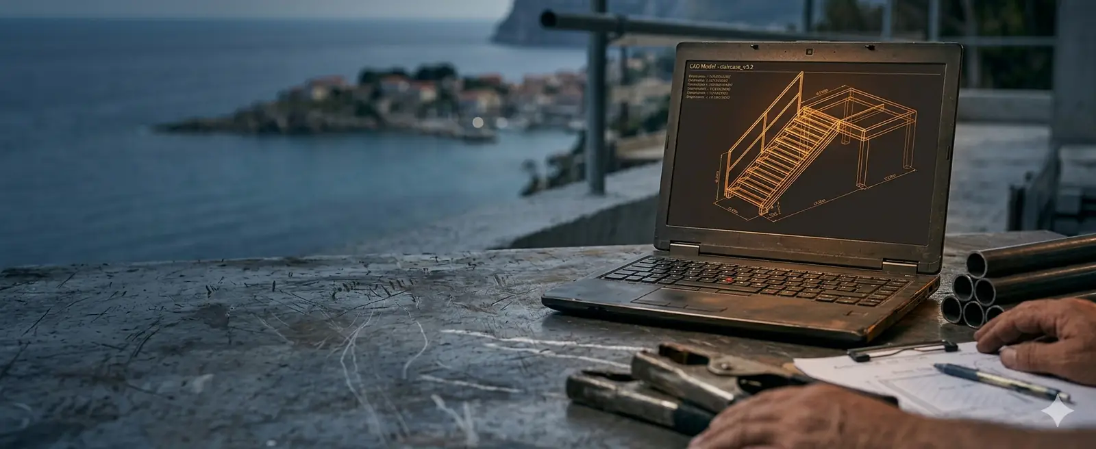
Nowadays, when raw-material prices are wild, every estimating error cuts straight into your profit. That is why serious work no longer starts without a digital twin of the future object — a 3D model from which an absolutely accurate specification is extracted before the first tube even arrives at your workshop.
Paper tolerates anything, the workshop does not
In the traditional approach, architectural drawings (2D) often give only basic dimensions. On paper everything looks perfect: lines meet, dimensions add up, and connections seem feasible. But when that paper reaches the workshop, the problems begin. A two-dimensional drawing rarely shows the real profile thicknesses at connections, the position of bolts in corners, or sheet overlaps.
Professional 3D modelling solves this because the object is literally "built" in the computer at 1:1 scale, with all the real wall and material thicknesses. If two beams collide at an awkward angle, the software shows it immediately.
We solve the problem at the screen, instead of your fabricator solving it with an angle grinder on site — when it is already too late.
Accurate material specification: the end of guesswork
One of the biggest fears in larger projects is ordering material. Whether you order too little or too much, both scenarios eat directly into your profit:
Order 10–15% more "just in case" and that surplus eats up a good chunk of your margin.
Order too little and you lose days waiting for a new delivery — plus extra transport cost.
When we build a 3D model of a steel structure, the software automatically and flawlessly generates a Bill of Materials (BOM) — an exact specification of all required positions, profiles, sheets, and even the number of bolts and nuts. We know the exact length of every position to the millimetre, as well as the total weight of the structure you need for ordering a truck and crane.
Based on that specification you can create an ideal cutting list (nesting) and order exactly as many 6- or 12-metre bars as you really need, with minimal waste.
Solving "clashes" and installation problems in advance
On-site installation is the most expensive part of the job. Every hour of downtime on site costs — you pay the crew, the crane, the tools and the per diems. If it turns out on site that the holes in the flanges do not line up or that a diagonal blocks a pipe run, you lose money.
A 3D model enables "clash detection" — the computer analyses the whole assembly and warns if a bolt cannot be tightened because there is no room for a wrench, or if two diagonals intersect in the wrong place.
The model also lets us divide the structure into assemblies (segments) adapted to transport and to the maximum capacity of the forklift or crane that will be on site.
Project visualisation: what the investor is actually buying
If you work directly with the end customer, you know how hard it is to explain a technical drawing to the average person. Most people cannot read floor plans and sections and cannot picture how their canopy, hall or designer staircase will look in the space. This often leads to misunderstandings and the classic situation: "But I thought it would be different."
Here project visualisation plays a key role in selling and protects you as the contractor. We can turn the finished 3D model into a clear, attractive 3D render or an interactive model the investor can rotate on their phone. When the customer sees a realistic view of the connections, profile type and proportions in advance, every doubt disappears.
With a signature on such a visualisation you are protected from later complaints about the design — the customer saw and confirmed exactly what they are buying.
The basis for workshop drawings and DXF files
A 3D model is not just a "nice picture" for presentation — it is the basis for everything that follows. Once the model is finished and confirmed, 100% accurate documentation is automatically extracted from it:
For the saw and the drill — each part with exact dimensions and hole positions.
For the workbench and the site — the logic of assembly and installation.
For all sheet-metal positions — send them straight to laser or plasma.
No redrawing, no manual copying of dimensions and no human error in transferring data. This is the level of professionalism that turns a small workshop into a serious player on the market. Read more about what documentation contains in the article on workshop documentation.
Conclusion
Skipping 3D modelling before ordering material may seem like saving time and money at the very start, but it is actually the most expensive gamble in the whole project.
Investing in a precise 3D model pays off many times over through optimal material ordering, calmer production and fast installation without unpleasant surprises. See indicative prices for model creation in the price list.
Request a 3D model